 Home Page
Can-Am Spyder Wheel Alignment Gear
 Spyder front wheel alignment equipment.
To perform your own Spyder front wheel alignments you need to build some essential equipment:
Targets:
You will need two laser targets. These are simply 300 x 140mm plywood screwed to a wooden ‘foot’ and a vertical center-line added. Also, at 270mm from the floor – that’s hub-center height – add a scale each side of the center-line in 5mm gradations out to 20mm... you’ll never need any bigger measurements! Don’t paint the targets black – that just makes the laser dot hard to see in daylight. White is good, and if you mark your scale on a piece of aluminium sheet glued to the target, that’s even better. The laser dot shows up well on a slightly reflective surface. You can also use a set-square ( side-on ) as a narrow extra laser target. See the Kit instructions for details.
Wheel Standoffs:
You need a pair of them. It cost me only $35 to have a local sheet-metal firm cut two circles out of mild steel. I chose 250mm Ø so that the legs could be attached at 230mm Ø – ideal for Spyder brake discs. The leg centers are fairly close to the rim of the brake discs on both <2012 or 2013> models ( slightly different disc sizes ).
Steel standoff plates are heavy. Mine were cut from 3mm steel plate – 4mm would be sturdier, but also 33% heavier. Each 250mm Ø plate weighed 1.2kg. If you are making your own, plain circles would be fine, and weight might not be a concern. But I was worried about weight, so cut slices off three edges of the steel discs to make ‘stubby triangles’ leaving a clear 180mm Ø in the center for attaching 6” laser levels ...that brought them down to about 900g per plate, which is acceptable for a Kit designed to be posted around the country.
The second major improvement was adding rare-earth magnets to the heads of the M8 bolt legs, so that they stick to the brake disc without straps. Rare-earth magnets are $14 for a pack of 4 – so two packs were needed. Two of the M8 bolt legs for each standoff also have an alloy L-collar under the bolt head, which projects a ‘finger’ over the upper rim of the disc. The magnets do adhere very strongly, but brake discs are shiny and smooth, so the L-collars prevent the legs sliding down.
The L-collars were made from 12 x 3mm aluminium bar at 12mm length from leg-center to ‘finger’ to ensure correct placement on the brake disc. They can be twisted to cause the standoff legs to touch the brake disc in different positions but, generally, the standoffs sit a couple of millimeters lower than central on <2012 models, and a couple higher on 2013> models.
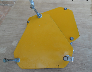
Each assembled standoff is a steel plate with 3 equi-length bolts at symmetrical 120° spacing to form legs, so that it will fit 3-spoke, 6-spoke or 12-spoke wheels, and can be rotated to suit any spoke design.
Calibrating the standoff:
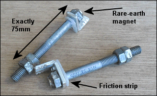
This is all about getting the 6 legs exactly the same length. First file or grind the M8 bolt-heads flat to remove any raised lettering, then attach a 10mm diameter rare-earth magnet to each one. Use only a thin skin of epoxy under the magnet so that it sits exactly flat, but later add extra epoxy around the outside of the magnet to ensure a solid, robust join. Next, use an accurate measurement tool such as a vernier caliper, set to 75mm (See Update June 2020, below). In turn, place each of the 6 bolt-legs in a vice with part of the bolt-head protruding above the vice jaws. Screw 2 nuts right down, then paint some Locktite or similar on the thread at the 75mm height and, using your caliper ( or depth gauge ), turn the top nut back so that the top of the nut is exactly 75mm from the exposed face of the magnet attached to the bolt-head.
 Hold that nut in a spanner ( about half a flat back toward the bolt-head, because turning a lock-nut against it will cause it to spread outward on the thread a little ) and turn the bottom nut up against it with a second spanner so that they lock together. Re-measure and repeat until you get it perfect. Using lock-nuts also held by Locktite makes them pretty solid, and gauging the leg height this way ensures that all 6 legs are identical. This gives you 75mm from the magnet ‘foot’ of each leg to the underside of the standoff plate – that’s enough for spoke clearance on any of the different Spyder wheel types (See Update below).
Update June 2020: Some Spyders and Rykers have different wheels with spokes that protrude a little further than older models, so I would now recommend making the standoff legs about 10mm longer than shown here – instead of 75mm to the underside of the standoff plate, 85mm would be safer!
This picture shows two standoff legs, showing the rare-earth magnets epoxy-glued to the bolt-heads, plus the L-collars, showing the strip of polyethylene pop-riveted to the arm of the collar to provide friction drag. These allow the collars to be twisted to a convenient angle to match the disc rim. Alternative: Instead of L-collars to prevent sliding, you might use something simple like a rubber door-stop between the spokes on one of the stand-off legs... anything that stops the whole stand-off from sliding down.
Attaching the standoff:
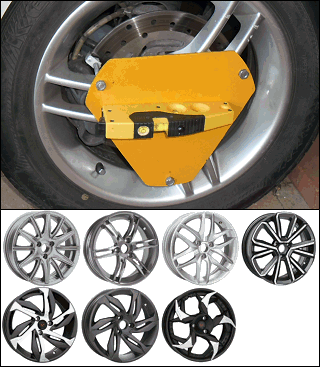
Simply poke the standoff legs through the gaps between spokes so that the legs touch the brake disc, with the L-collar ‘fingers’ of the top two legs sitting on the disc rim, one leg adjacent to the brake calliper housing. Rare-earth magnets are very strong, and hold the standoff in place against the brake disc firmly.
These standoffs should fit all the Spyder wheel types that are symmetrical, like the straight-spoke wheel types illustrated in the top row here. The wheel types that have curved spokes, like those on the bottom row, are more difficult, but the legs will still fit through, although you may need to rotate the standoff a bit to find a clear entry. The ‘Blade’ type illustrated bottom right is unknown, and has 5 spokes, so may present a problem for the symmetrical standoff design.
What else do you need?
- Two 6” magnetic-base laser-levels. If ever buying replacements for the yellow plastic Shinty levels I would choose either Silverline 210mm Laser Levels for around $30 each ( adjustable up-down pitch ), or Bosch PLL 1P models at around $45 each ( cast alloy frame and can stand a bit of rough treatment ). Models that project a dot ( not a cross-hair ) are essential.
- a set-square;
- a tape measure;
- masking tape;
- 2 ratchet-straps ( about $4 each );
- Open-end spanners. For tie-rod lock-nuts, an 18mm spanner ( an odd size )*; for actual tie-rods, a 10mm and/or a 16mm spanner for older-model and/or newer-model Spyders.
You’re not going to stretch your finances much buying this gear!
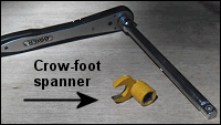
* A normal, flat 18mm spanner is all you need for <2012 models. But for 2013> models, you also need an 18mm crow-foot spanner ( see Alignment Kit instructions ) to get at the inner tie-rod lock-nut on the left side... there is just not enough room to use an ordinary 18mm spanner, because you can’t get at the nut from below as with earlier models – you have to access it from the side.
You can make a crow-foot spanner by welding an 18mm open-end spanner onto an old socket, then grinding off the spanner handle. If you don’t have welding gear, your local engineering shop would do that job in 10 minutes.
Or do an online search for an 18mm Crowfoot spanner. They are available to suit a ½” or a 3/8” drive for less than $20.
Aligning magnetic laser levels: They should be perfect straight out of the box, but to check... use a flat surface at least 2 meters long ( longer if possible ). NOT a drop-leaf surface like a dining table – that is not truly flat. Place both levels alongside each other, magnets downwards, and measure the distance between the beam and the surface right by the lasers... then measure them again 2 meters or more away. Place the levels at the opposite end of the flat surface, pointing the other way, and repeat that. This will show whether the levels are accurate on that vertical plane, or whether they need adjustment. This up-down accuracy is all that is important – because once the magnetic-base level is attached to the wheel standoff it is then lying on its side, and up-down becomes left-right, which is what matters for wheel alignment.
- NOTE: Scale matters. If your laser level is out by as much as half a laser-dot over a 2-meter distance ( a rare thing ) that translates to an error of only 0.1mm at the wheel because of the 5-times magnification factor with the targets being 5 times the diameter of the wheel away. Really, such a tiny error that it’s not worth worrying about.
If you are building your own alignment gear and have questions, do not hesitate to email me – use the ‘Email Me’ button at the top right of this page. To my knowledge, 8 owners have now made their own wheel alignment equipment based on the descriptions here. One in NZ, two in Tassie, one in Vic, one in Qld, one in NT, one in WA, and two in the USA. It really ain’t rocket science...